
For the past year or so, I’ve been learning shader programming and, in particular, how to use Signed Distance Functions (SDF) as a way of generating shaders for various art and science projects. Before I discuss my explorations, let’s discuss the basics of SDFs.
Statement of the Problem
Let’s try to render an image using mathematics. Where do we begin? Well, let’s talk about the display first.
Let the top left pixel be at “uv coordinate” (0, 0), the pixel to its right is (1, 0), the pixel below it is (1, 1), etc. Now imagine you treat it like a vector field; given the pixel uv coordinate (x,y), what is the 4-vector (corresponding to the pixel’s red, green, blue, and alpha values at that spot) that generates the image you’re trying to make?
This process is very math heavy, but not in the way you might think. In vector art (think Inkscape), each vertex, curve, area, etc., is also defined by math, but the pipeline for defining it, the pieces of hardware that compute it on your computer, and how it eventually creates the image is entirely different. In brief, the data lives on your hard drive and/or RAM, it gets processed by a CPU (or maybe even GPU), the processed image data gets sent back into memory, and then eventually the image data gets piped out to the screen… uh… somehow. I’m not sure after that. The point, however, is you don’t have to know/care how, and no GPU is needed, and you store the data “independent” of the screen it is used on.
For SDF rendering, however, you can imagine each pixel has its own mini-computer inside of it (that’s GPU programming for you), so you can write math snippets per-pixel and it will directly render it to the screen without sending data anywhere. This is a tradeoff, as not needing to send this data anywhere makes it fast (hence why we use it to render). It also means, however, that you can’t extract information from the data processed in the “pixel-computer.” More to the point, however, is that you need to somehow coordinate an image across pixels using the exact same program across all pixel-computers.
That should sound like a hard problem to you. The exact same program running on every pixel somehow creates an image? How do you even do that? One answer: SDFs.
Signed Distance Functions: A Primer
Let’s define the center of the display as the uv coordinate (0, 0) and begin by visualizing the distance each pixel is away from the center. The program we write could be something like “the distance a pixel at uv-coordinate (x,y) is from the center of the screen can be visualized as a value ranging from black to white, with further distances being more white.” What does this image look like? A black, fuzzy circle.
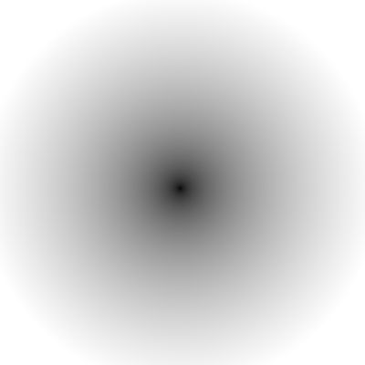
Figure 1: Point Distance Field. The distance of the center from the center is 0, so it is black. The further a pixel is from the center, the greater the value, and so the whiter it becomes. Let the 2d dependent variable be \( uv=(x,y) \), and the 4d independent variable be \( color= (r, g, b, a) \). Then this image is created with \( c = \sqrt{x^2 + y^2}, color = (c, c, c, 1) \)
You might think that if I ask you to subtract a constant from the SDF (let’s say -0.5) that everything would get darker. Perhaps that’s true, but it isn’t all that happens, as the image actually expands the point to a circle. After some thought, it should be obvious why this happens (hint: there’s a locus of points that used to be at 0.5 that’s now at a value of 0).
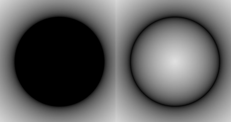
Figure 2: The Point Distance Field expanded to a circle. The left image corresponds to the equation \( c = \sqrt{x^2 + y^2} – r, color = (c, c, c, 1) \). The right image is just the absolute value of the left; notice how negatives are rendered as black. Note: I’ve actually taken the square root of \( color \) to make these images visually “cleaner” from an artistic point of view.
You can abstract this concept using more sophisticated math to generate a variety of distance functions corresponding to various shapes; see this page by Inigo Quilez for more details, if curious. The important point, however, is that this is a mathematical minimization process; for a given point, we want the minimum distance from ALL curves defined by the set of SDFs.
The Point of This Post
A fundamental tool for math, rendering, and many other fields is the use of boolean operators– things like intersection and union and difference (see this as a primer). One of the things that tripped me up early on with shader programming, however, is the following: While you CAN perform boolean operations on SDFs, the resulting object may not itself be an SDF. The first question is how we define the boolean operators.
Let’s start with Union (think Venn Diagram). Imagine I have two separate circle SDFs separated by some distance. Each one of these in isolation would be a black disk with fuzzy edges, and so we expect the union of the two images to be two black fuzzy disks that may have some overlap. To do this, we actually just compute the minimum of the two SDFs. Notably, because the SDF is itself just a minimization problem, we’re lucky to find that the resulting object is, itself, an SDF. Yay!
This ends up being true for the Intersection as well. If we replace our attempt at finding the minimum with finding the maximum, we get the intersection. But how do we know that it is, in itself, an SDF? Well, you could instead imagine multiplying both individual SDFs by -1, which then makes low magnitude negative values greater than high magnitude negative values (e.g. -2 > -3). And since the negative of an SDF is itself just an SDF, we can take the min of the negative SDFs (which is the max of the positive ones), which is guaranteed to be SDF itself. Then, we just multiply the resulting SDF by -1 again to flip it back “to normal”.
Now what about differences? Notably, there is no simple sign-flipping and/or combinations of min/max that can help us. As you can see in the image below, the inside of the “crescent moon” looks legit, but the outside has this weird cusp. Why?
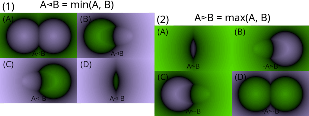
Figure 3: Various combinations of min and max operations acting on two individual circle SDFs. Purple represents negative numbers, green positive. In panel (1), we are taking the minimum of the circles, where each panel is some combination of of positives and/or negatives of the original circles. Note that panels (A) and (D) are SDFs, but (B) and (C) are NOT SDFs. The question is: can we make images from simple differences (or something similar) of the original images that result in SDFs, or is it fundamentally impossible? The answer is no one knows at this time.
No clue. And no one else knows either; no one is currently able to make images from simple differences (or something similar) of simple SDFs that result in SDFs. Why does anyone care? Well, if you were to try and write an SDF based rendering program for artists (think blender), they wouldn’t have access to fundamental tools the way traditional 3d art programs do. And hence, this is why you don’t see SDF based rendering used as any backbone to any major 3d software.
I think SDF based rendering is beautiful from a physics perspective, though, and so I’m currently playing around with trying to find some solution to this problem. I’m nowhere near a solution, but I did write a quick interactive shader that illustrates why you get that “lip” on the outside of the crescent; check it out.
(This post was sent to no one, so I doubt anyone will read it, but still).